555 Timer Schematic - 555 Timer Ic Testing Circuit And Its Working - If you want to know all the pinout of the 555 timer, what each pin is and what each pin does, see 555 timer pinout.
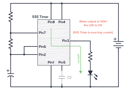
555 Timer Schematic - 555 Timer Ic Testing Circuit And Its Working - If you want to know all the pinout of the 555 timer, what each pin is and what each pin does, see 555 timer pinout.. The breadboard schematic of the above circuit is shown below. In this mode, the circuit of the ic 555 timer produces the continuous pulses with exact frequency primarily based on the value of the two resistors and. Each mode of operation indicates a circuit diagram and its output. The time intervals can be used for keeping a relay controlled load on or activated for the desired amount of time and an automatic switch off once the delay period. The 555 timer ic is an integral part of electronics projects.
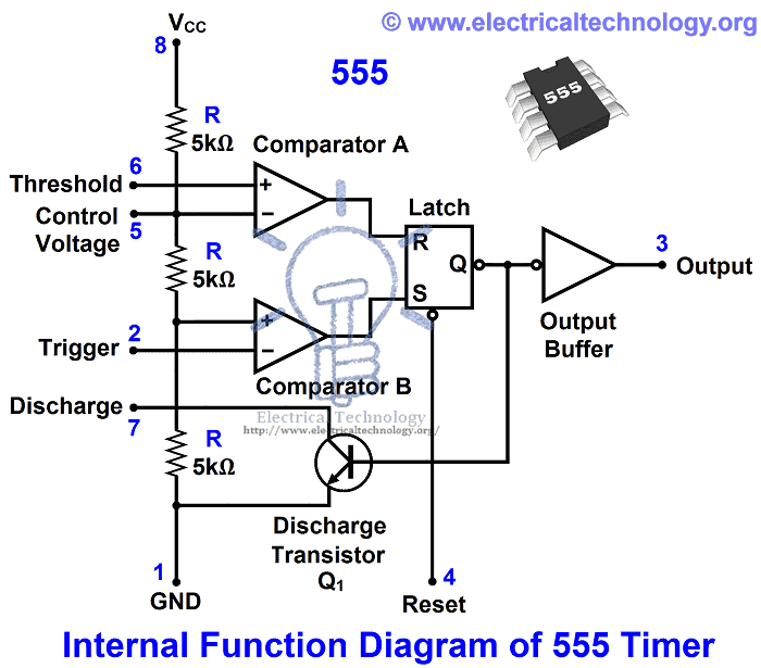
555 timer is an industrial standard ic existing from early days of ic. In this circuit, we will connect the 555 timer to be in astable mode. 555 timer circuits (133) browse through a total of 133 555 timer circuits and projects including the timer's datasheet. We have a large collection of simple and advanced projects using 555 timer ic. The block diagram of a 555 timer is shown in the above figure.
555 Timer Ic Types Construction Working Applications from www.electricaltechnology.org 500ms is the same as saying 0.5s so by rearranging the formula above, we get the calculated value for the resistor, r as: Derivatives provide two or four timing circuits in one package.it was commercialized in 1972 by signetics. The 555 timer is a simple integrated circuit that can be used to make many different electronic circuits. Working modes of 555 timer ic. Being an integral part of electronics project, 555 timer ic is very often used in simple to complex electronics projects. Figure 2 shows the basic 555 timer monostable circuit. The 555 timer ic is an integral part of electronics projects. The 555 is also very versatile, and can be used.
In this circuit, we will connect the 555 timer to be in astable mode.
555 timer is an industrial standard ic existing from early days of ic. In 2017, it was said over a billion 555 timers are produced. These on off intervals can be adjusted by varying the 555 timer output and number of counter outputs. The block diagram of a 555 timer is shown in the above figure. Using the 555 timer ic in special or unusual circuits. The circuits explained here are 10 best small timer circuits using the versatile chip ic 555, which generates predetermined time intervals in response to momentary input triggers. 500ms is the same as saying 0.5s so by rearranging the formula above, we get the calculated value for the resistor, r as: The values of r1 and c1 determine how long the output will remain high. To understand the basic concept of the timer let' s first examine the timer in block form as in figure 1. Its name is derived from three 5k ohm resistors ,connected in series used in it.the timer ic can produce required waveform accurately. In this project, we are using 555 timer ic to create various timer circuit like 1 min timer circuit, 5 min timer circuit, 10 min timer circuit, and 15 min timer circuit. The time intervals can be used for keeping a relay controlled load on or activated for the desired amount of time and an automatic switch off once the delay period. This circuit uses very basic components like 555 timer and 4017 counter.
To understand the working of the 555 timer in astable mode, take a look at the internal circuit of. This pin should be connected to ground. To understand the basic concept of the timer let' s first examine the timer in block form as in figure 1. The second 555 timer helper will extend the timers output duration without having to use large values of r1 and/or c1. 555 timer is an industrial standard ic existing from early days of ic.
555 Timer Tutorial And Circuits Build Electronic Circuits from www.build-electronic-circuits.com The 555 timer delay before turn on circuit we will build is shown below. Let us discuss in detail about this circuit. Basic 555 monostable multivibrator circuit. 555 timer helpers schematic the addition of a capacitor to the trigger will not work for short output pulses as there is also a short delay in the recovery of the trigger terminal voltage. The breadboard schematic of the above circuit is shown below. With this information you will learn how how the 555 works and will have the experience to build some of the circuits below. Once this switch is pushed, the circuit pulls its output to a. In this circuit, we will connect the 555 timer to be in astable mode.
With this information you will learn how how the 555 works and will have the experience to build some of the circuits below.
Working modes of 555 timer ic. Before going into detail of time delay circuit, first we need to learn about 555 timer ic first.below you can find the pin diagram of 555 timer ic along with the details of each pin. Derivatives provide two or four timing circuits in one package.it was commercialized in 1972 by signetics. In this category, we have handpicked some really useful 555 timer circuits which will be interesting to electronics engineering students and hobbyists alike. The block diagram of a 555 timer is shown in the above figure. 555 timer helpers schematic the addition of a capacitor to the trigger will not work for short output pulses as there is also a short delay in the recovery of the trigger terminal voltage. If a 10uf timing capacitor is used, calculate the value of the resistor required to produce a minimum output time delay of 500ms. This pin connects to the negative side of the battery. The circuits explained here are 10 best small timer circuits using the versatile chip ic 555, which generates predetermined time intervals in response to momentary input triggers. The following image shows a simplified circuit of 555 timer ic in astable mode. The working modes of a 555 timer are astable, bistable, and monostable. Figure 2 shows the basic 555 timer monostable circuit. As we know 555 timer ic is one of the commonly used ic among students and hobbyists.
As we know 555 timer ic is one of the commonly used ic among students and hobbyists. The 555 timer can be obtained very cheaply from pretty much any electronic retailer. In this circuit, we will connect the 555 timer to be in astable mode. Once this switch is pushed, the circuit pulls its output to a. Using the 555 timer ic in special or unusual circuits.
555 Timer Circuits Posts Facebook from lookaside.fbsbx.com The block diagram of a 555 timer is shown in the above figure. The time intervals can be used for keeping a relay controlled load on or activated for the desired amount of time and an automatic switch off once the delay period. Simple 555 timer circuits & projects. To understand the working of the 555 timer in astable mode, take a look at the internal circuit of. The timer's internal circuitry is largely responsible for this triggering but it is also caused stray or installed capacitance at the trigger input of the timer. We have seen in the last few tutorials that the 555 timer can be configured with externally connected components as multivibrators, oscillators and timers, with timing intervals ranging from a few microseconds to many hours. 555 timer helpers schematic the addition of a capacitor to the trigger will not work for short output pulses as there is also a short delay in the recovery of the trigger terminal voltage. For detailed explanation, check it out.
Daman shah june 5, 2021.
In this project, we are using 555 timer ic to create various timer circuit like 1 min timer circuit, 5 min timer circuit, 10 min timer circuit, and 15 min timer circuit. For detailed explanation, check it out. Resistive network consists of three equal resistors and acts as a voltage divider. There are simple circuits for beginners and advanced engineers. 555 timer astable mode circuit diagram. Working modes of 555 timer ic. Basic 555 monostable multivibrator circuit. The working modes of a 555 timer are astable, bistable, and monostable. Adjustable on off timer(using 555 astable mode) in this circuit a timer with cyclic on off operations is designed. The block diagram of a 555 timer is shown in the above figure. If a 10uf timing capacitor is used, calculate the value of the resistor required to produce a minimum output time delay of 500ms. The 555 is also very versatile, and can be used. Using the 555 timer ic in special or unusual circuits.


0 Komentar